Type of Injection mold parting line
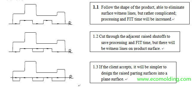
1.Horizontal parting line

2.Oblique parting line

3.Curve parting line

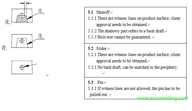
4.Injection mold parting line on shut off holes

5.Injection mold parting line on side holes

General Principles for Selection of Main Parting line
- Protect the Inserts
Usually, product disassembly needs to be considered before selecting the main parting surface, i.e. identify the secondary parting surfaces, and find out the lowest surface of the cavity insert which will serve as the main parting surface. Try not to let the cavity core enter plate B from plate A, so as to prevent the insert from being damaged during mold disassembly.
- Simplify mold structure, increase mold plate strength
- Identify the main parting surface based on the special structure of a plastic mold
- To prevent the parting line locks on the 4 corners of the insert from being wrongly assembled, the lock at the base corner needs to be 1.0mm larger.
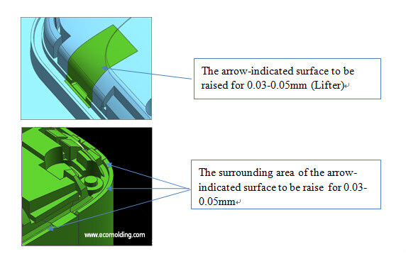
- When the main mating surface of a product exists on 2 work pieces concurrently, the piece inside the profile surface needs to be raised for 0.03 – 0.05mm, so as to prevent apparent mismatch. (See the following figures)

- At the joint between the core and the cavity, the melt in the cavity needs to be reduced by 0.03-0.05mm, so as to prevent mismatch of product kiss-off holes caused by processing tolerances.
General Principles for Selection of Secondary parting line
- Meet client needs, without affecting product appearance & performance
- Convenient for mold release
- Facilitate venting
- Minimize side undercuts, simplify mold structure
- Convenient for processing
- Convenient for surface treatment of the mold insert
