Differences Between CPVC and PVC

Polyvinyl chloride (PVC) and chlorinated polyvinyl chloride (CPVC) are both common plastic materials. Although their names sound closely related, their actual properties differ significantly. Polyvinyl chloride is abbreviated as PVC, while chlorinated polyvinyl chloride is known as CPVC, with the additional “C” indicating chlorination. Comparing these two materials is somewhat like comparing ordinary glass with tempered glass: they share the same base material, but special processing gives them very different properties.
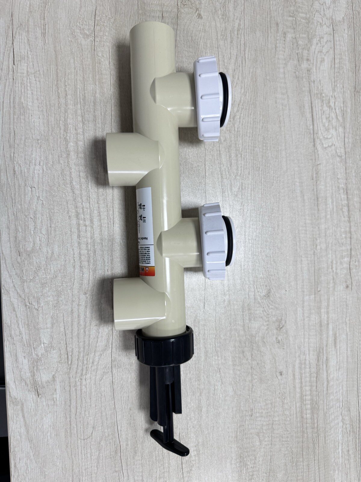
CPVC vs PVC pipe comparison

Material Composition

In terms of material composition, PVC is a basic plastic formed through the polymerization of vinyl chloride monomers, while CPVC undergoes a secondary chlorination process based on PVC. This process does not simply involve adding chlorine gas; instead, chlorine atoms replace some hydrogen atoms, increasing the chlorine content from about 56% to 63–69%. This change in molecular structure gives the material new properties, the most notable being improved heat resistance. Standard PVC pipes begin to soften at temperatures above 60°C, whereas CPVC pipes can continuously withstand temperatures up to 93°C and tolerate temperatures as high as 110°C for short periods. When selecting materials for hot-water piping systems, this temperature difference directly affects service life.

Corrosion Resistance

Corrosion resistance is another key difference. Both materials resist acids and alkalis, but CPVC performs better against strong acids and strong alkalis. Concentrated sulfuric acid above 40% concentration gradually degrades PVC, while CPVC remains stable. Pipes used to transport corrosive media in chemical plants are therefore commonly made from CPVC, whereas standard PVC is more suitable for residential wastewater drainage. In one real-world example, wastewater pipes in an electroplating workshop made of PVC became deformed and began leaking after only three months. After they were replaced with CPVC pipes, they remained in good condition even after two years of use.Their applications also differ significantly. PVC is commonly used in water supply and drainage pipes, electrical conduits, and uPVC window frames, while CPVC is more widely used in industrial settings. Hot-water circulation systems in power plants, steam pipelines in food-processing facilities, and ultrapure water delivery systems in semiconductor plants are all typical applications where CPVC performs best because these environments require high-temperature resistance or high-purity processing. One detail worth noting is that CPVC pipes are usually light gray, whereas PVC pipes are typically white or dark gray. Care should be taken not to confuse the two during installation.

Installation Methods

Installation methods also differ. PVC requires surface preparation before adhesive bonding, while CPVC, due to its denser surface structure, must be bonded using a specialized solvent cement. For heat-fusion welding, PVC is typically welded at around 215°C, whereas CPVC requires temperatures closer to 260°C. One construction team once welded CPVC pipes using the temperature normally used for PVC, resulting in fine cracks at the joints that later caused leakage when water was introduced into the system.Price is another important consideration. The raw material cost of CPVC is typically 30–50% higher than that of PVC. In industrial applications, this additional cost is generally acceptable because of the substantial performance benefits. For residential renovations involving only cold-water systems, however, there is usually no need to pay extra for CPVC. That said, for the piping section upstream of a floor-heating manifold, CPVC is often the safer choice because it remains in long-term contact with high-temperature water.

Fire Resistance

The difference in fire resistance is also worth noting. PVC has an oxygen index of around 45% and will self-extinguish once the flame source is removed. CPVC has an oxygen index of approximately 60%, making it more difficult to ignite and producing less smoke during combustion. If plastic materials are used for oxygen supply pipes in hospital operating rooms, CPVC is considered the safer option. In one laboratory comparison test, CPVC pipes ignited 15 seconds later than PVC pipes under the same flame conditions.

Service Life & UV Resistance

Service life is strongly affected by environmental conditions. Under prolonged exposure to ultraviolet radiation outdoors, standard PVC tends to yellow and become brittle, whereas CPVC offers better UV resistance. In one residential complex in northern China, downspouts made from both materials were installed at the same time. After five years, the PVC pipes had developed cracks, while the CPVC pipes showed only slight surface fading. However, when buried underground, the difference in service life between the two materials is minimal, and both can typically remain in stable service for more than 50 years.

Recycling

There are also differences in recycling. PVC recycling technology is relatively mature, whereas CPVC, because of its higher chlorine content, releases more hydrogen chloride gas during thermal decomposition and therefore requires specialized processing equipment. A factory in Germany developed a low-temperature decomposition technology for CPVC that converts recycled material into building insulation wool, although the cost is roughly twice that of landfill disposal.

Operating Temperature

When selecting materials, the temperature of the conveyed medium must be considered. Pipes carrying 80°C hot water must use CPVC, while standard PVC is entirely adequate for room-temperature liquids. One example involves the outlet piping of a solar water heater. The system originally used PPR pipes, which were prone to scaling. After switching to CPVC, scaling was reduced and the need for additional insulation was eliminated. It should also be noted that CPVC has a lower low-temperature embrittlement threshold than PVC, so outdoor applications in extremely cold northern regions require freeze-protection measures.

Chemical Stability

In terms of chemical stability, CPVC has better resistance to oxidizing agents. Sodium hypochlorite solution, commonly used for swimming pool disinfection, can corrode PVC pipes at high concentrations, whereas CPVC pipes do not face the same issue. During a renovation project at a water park, all disinfectant transfer pipes were replaced with CPVC, and the system operated for three years without abnormalities. However, CPVC is actually less resistant than PVC to ester- and ketone-based solvents, so extra caution is needed when the material comes into contact with such chemicals.

Dimensional Stability

Differences in dimensional stability are reflected in thermal expansion coefficients. CPVC has a linear thermal expansion coefficient of 0.062 mm/m·°C, lower than PVC’s 0.08 mm/m·°C. In long-distance pipeline installations, CPVC therefore requires fewer expansion joints. One industrial park installed a 300-meter steam-traced pipeline and reduced the number of expansion joints by 15 by using CPVC instead of PVC, significantly lowering installation costs.

Processing & Molding

Processing techniques also differ. PVC has an injection molding temperature range of 160–190°C, while CPVC requires temperatures of 190–230°C. In mold design, CPVC has poorer flowability than PVC and therefore requires larger gate dimensions. One manufacturer attempted to produce CPVC components using a mold designed for PVC, which resulted in incomplete filling (short shots). The issue was resolved only after the mold temperature was adjusted.

Drinking-Water Safety

With regard to drinking-water safety, both materials meet hygiene standards. However, CPVC releases fewer extractable substances, which is one reason direct-drinking-water systems in Japan tend to favor CPVC piping. One comparative experiment showed that, under identical conditions, the total organic carbon (TOC) value of water exposed to CPVC pipes was 40% lower than that of water exposed to PVC pipes, indicating lower organic leaching. CPVC is therefore recommended for infant drinking-water equipment, although many parents are unaware of this detail.

Impact Strength

When it comes to impact strength, PVC has a slight advantage at room temperature. CPVC is harder, but it is also more brittle. An interesting phenomenon can be observed when pipe fittings made from the two materials are struck with a hammer: PVC pipes tend to dent, whereas CPVC pipes may crack or even shatter. Special care is therefore required during installation, as CPVC pipes cannot withstand severe impact.

Pressure Resistance

In terms of pressure resistance, CPVC pipes generally offer higher pressure-bearing capacity than PVC pipes of the same specification. A DN25 CPVC pipe can safely operate at 1.6 MPa, whereas a PVC pipe of the same size typically withstands only about 1.0 MPa. Using CPVC pipes in the water supply systems of high-rise buildings can therefore reduce required wall thickness. In one 30-story apartment building project, switching from the original PVC design to CPVC piping reduced the total pipe weight by 15%.

Color Changes Over Time

Changes in color can indicate the condition of the material. After long-term UV exposure, PVC typically turns yellow first and then brown, while CPVC usually turns gray before becoming pale yellow. Experienced inspectors often use these color changes to assess the degree of pipe aging. In chemical plants, localized blackening on a CPVC steam pipe may indicate thermal decomposition caused by excessive temperatures and should prompt immediate inspection and repair.

Modified Grades

Both materials are available in modified grades. Common PVC variants include impact-modified and flame-retardant grades, while CPVC is also available in reinforced forms. Adding glass fiber to reinforced CPVC can triple its flexural modulus, making it suitable for large storage tanks. One environmental engineering company used reinforced CPVC to manufacture a 10 m³ pickling tank, achieving a service life five years longer than that of a traditional polypropylene (PP) tank.

Electrical Properties

In terms of electrical properties, PVC has a dielectric constant of about 3.2, while that of CPVC is approximately 3.0. This difference has little effect on ordinary wire insulation, but CPVC is often preferred for high-voltage cable insulation materials. One easily overlooked advantage is CPVC’s superior arc resistance, making it a safer material for electrical switch housings.

Industry Trends & Outlook

Finally, let’s take a look at future industry trends. Global annual PVC production exceeds 40 million tons, whereas CPVC production is only around 2 million tons. However, with ongoing industrial upgrading, demand for CPVC is growing at roughly 8% per year. Environmentally friendly chlorination processes and low-cost modification technologies have become major R&D priorities. A Japanese company recently introduced a bio-based CPVC material that replaces part of the petroleum-based feedstock with renewable resources. Innovations like these could reshape the industry landscape in the future.

Injection Molding Lifter: The Design Standard for Plastic Mold Tooling

Injection Molding Lifter Design in Plastic Injection Mold Tooling

The lifter is mainly used to form the internal undercuts of an injection molded plastic part, and at the same time it also offers ejection function. Considerations in lifter design include selecting abrasion-resistant and durable materials to withstand pressures and ensure operational efficiency. Ejector pins are essential for pushing molded parts out when the mold opens, particularly in scenarios with undercuts. The ejector plate moves upward to assist lifters during the ejection process, allowing molded products to be effectively released from the mold. Complex mold design is crucial as it directly impacts the injection molding machine’s lifter mechanism, especially when dealing with intricate product features like undercuts. The mold cavity plays a crucial role in shaping and solidifying the molten plastic, presenting challenges related to ejection mechanisms. The mold lifter features a simple structure but poor rigidity and a short travel distance. A simpler mold ejection mechanism, such as using inserts, can provide a more straightforward and efficient way to eject products. The lifter employs vertical and horizontal motion to facilitate the ejection of products, particularly those with undercuts. The typical structure is shown as below:

Most injection mold company usually apply the lifter structure as shown. The lifter employs the 8407 steel with a hardness of up to HRC50-52. There should be a distance of 1 – 3mm from the angle lifer to the product, with a clearance of 0.1mm on each side of the base made of the 738 steel, while the length tolerance is +1.5mm and +1.0mm on the top and bottom respectively.

At the end close to the melt flow, a 5.0mm plane surface has to be made (unnecessary when the part profile surface is plane), as well as a head that is bigger than (if not equivalent to) 1.0mm, to prevent the angle lifter from being moved by pressure during the injection molding process. A C0.2 chamfer needs to be set up on the mold core at the corner of the head.

The top of the lifter needs to be 0.03 – 0.05mm higher than the part profile surface, so as to avoid scratch during ejection.

Made of bronze, the wear block adopts the integral form and is installed under the B plate, with the main purpose to avoid lifter deformation and locate the angle lifter during the ejection process. The ejector retainer plate needs to be equipped with a limit column, which should be higher than the lifter base. When ordering a mold base for a injection mold designed with lifters, the spacer block needs to be higher, considering the travel distance of the angle lifter, so as to prevent insufficient travel distance.

Pantone Color Chart: The Matching System Guide

The Pantone Color Matching System is largely a standardized color reproduction system, providing resources and tools for accurately identifying and matching colors in design and printing. The importance of colour in customizing products and ensuring brand representation cannot be overstated. By standardizing the colors, different manufacturers in different locations can all refer to the Pantone system to make sure colors match without direct contact with one another.

This collaboration with clients across various creative disciplines and marketplaces showcases the global reach and expertise in providing color insights and solutions tailored to meet the specific needs of these clients. Selecting the right colours in graphic design and printing is crucial, and the Pantone Matching System is an essential resource for this purpose. The role of fabric and fabrics in product packaging and customized retail accessories is significant, though there are challenges in achieving certain shades on different types of fabrics.

The Pantone color charts are intended as guides and not definitive tools, urging reliance on physical color references for precise matching. It is important to note the limitations of digital color tools and the necessity of physical Pantone color references. Packaging plays a vital role in color accuracy for print and digital design. Print is significant in achieving the desired colors for printed items using the Pantone Matching System.

Printers and graphic designers use CMYK for accurate color selection and reproduction. A reference guide is essential for matching Pantone colors in printing. The use of a search function helps quickly locate specific Pantone color codes. Tools for color selection and conversion between different systems like RGB and Pantone are invaluable. Customers in the USA can purchase Pantone books from online platforms catering to the United States market. Various aspects of products and services vary depending on specific attributes or requirements. The global reach of the Pantone system serves clients worldwide, showcasing their expertise in color solutions.

Please click below link for Pantone color chart

PANTONE-color chart

Pantone color chart

What Causes Black Marks on Plastic? Understanding Specks/Streaks in Injection Molding Parts

black specks streaks

Black specks/streaks and impurities are the most important factors that lead to rejects in the normal production process. Stubborn stains mainly affect the appearance of the product and lead to scrap. Most of the impurities and black specks are usually caused by foreign substances, i.e., they have nothing to do with the raw material itself. Only a small portion of the black specks and impurities are caused by the raw material itself.    Black specks and impurities are characterized by small dark brown particles, which generally do not reflect light. When the particles are large, the impurities are layered, brittle, fragile and porous after being broken. Some of them are irregularly scattered on the whole, some are scattered randomly in local parts, and some only occasionally appear in a local area.

Impurities are divided into two major categories, the ones formed before and during the molding process:

Black Specks & Impurities Formed in Plastic Containers before Molding:

Due to various reasons, foreign substances are not cleaned during the processing of the raw material, leading to black specks on the raw material;

Impure granulation causes black specks;

The raw material is mixed with color masterbatch or speckled crushed blocks and scraps;

Impure material – low melting-point material is mixed with high melting-point material;

Impurities may be mixed in during packaging, transportation and storage, of which, the obvious feature is that after the raw materials are unpacked, you can see that there are foreign matters and impurities on the surface of the material pellets if you observe carefully;

Impurities and foreign substances during material feeding;

Carbonization of raw materials

With regard to carbonization of raw materials, the black specks are generally larger in volume, and the largest ones may reach 1-2mm in diameter. Most of the “black specks” are thicker, but there are also thinner ones consisting of one or two layers. This is usually caused by long-term raw material storage, or that the raw material is locally overheated, leading to decomposition, coking, and carbonization into agglomerates. It is formed after the material is crushed by shearing when flowing through the screw or the nozzle. Using chlorine bleach for cleaning raw materials can help prevent impurities.

Causes of Material Carbonization in Plastic Ware:

  1. The melt temperature is too high. If the temperature of the material is too high, it will cause decomposition and form carbides. Especially for some heat-sensitive materials with a very narrow temperature range, the temperature of the barrel must be kept moderate.

  2. Material coking: If the molten plastic stays in a certain place for too long a time, coking will occur, thus causing black speck. The areas that may cause material retention include joints between the nozzle and the barrel, the barrel wall, the melt ring, the connection between the nozzle and the gate, the corner of the hot runner, and the dead corner in the sprue, etc.

  3. The barrel clearance is too large – the gap between the barrel and the screw is too large, which will cause the material to stay in the barrel, and the retained material will decompose after long-term overheating, thus leading to black specks. Cleaning the barrel and screw with hot water can help prevent carbonization.

  4. Additives discolor due to degradation and decomposition. Additives include antistatic agents, violet / infrared absorbers and general dyes. Their properties are generally more active than the raw material. Under the action of the shearing force at the processing temperature, they have already been decomposed into dark, brown, and even black colors, presented as black specks and impurities after plastic injection molding.

Black specks and impurities due to external causes are very common in production, and they are very stubborn stains after occurring.

  1. The mold material is not good, with iron powders falling off the parting surface, the molding surface or the kiss-off surface, thus causing black specks. Use a damp cloth to clean molds and other parts to prevent impurities.

  2. The ejector pin is rough and easy to burn, causing iron powders to fall off and thereby the black specks.

  3. The slider generates iron powders, leading to black speck.

  4. The slider rusts or generates other stains due to water leakage inside the slider, which are thrown out by slider movement, and black speck are caused when they fall onto the product.

Distinguish the Black Specks:

If the black speck appear on both the entire product surface and in the depth of the part, they should be formed before injection molding; if the black specks only appear on the surface, they should be formed during injection molding. If at the same time they are only distributed in a specific area of the surface, it is undoubtedly that they are black specks formed during the injection molding process; if the black speck are large (generally 0.5- 1mm), it should be caused by material carbonization; if they are also dark, brittle and porous, it can be confirmed that they are caused by carbonization: if the black specks are particularly dense and the raw material is checked for no obvious impurities, it is usually caused because the previous material is not immediately cleaned before the material change, otherwise the material should be looked into to identify the reason.

Solutions for Removing Stubborn Stains:

  1. For impurities in a molded product, black specks are caused due to foreign substances mixed in the raw material, so the cleanliness of all the links, including production, packaging, storage, transportation, unpacking, material mixing and the barrel, must be strictly controlled. Using a baking soda paste can effectively clean plastic containers and remove stains, ensuring that all surfaces are free from stubborn residues.

  2. For black specks caused by carbonization, the injection temperature should be strictly controlled.

  3. Usually, for the black speck caused by additive degradation or the ones caused by the existing carbonized materials deposited on the screw surface and the screw barrel wall, they can be removed from the original location into the molten material under various strong shearing effects in the screw barrel during the production process. The “removal” is a process in which black specks and impurities appear in the product. When changing materials or colors, if this impurity “removal” process is inevitable, we must try our best to minimize it, i.e., “cleaning.”

Injection Molding Defects Causes and Remedies PDF: A Guide to Countermeasures

April 6, 2018

The causes and countermeasures described below are aimed to solve the common injection molding defects that might occur in ordinary circumstances. The examples are just based on my own personal work experience, so if there is anything inappropriate, you are welcome to correct me!

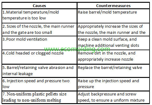
Short shots (incomplete filling) – injection molding defects

(1) Short shots (incomplete filling): The molten plastic fails to fill up each and every corner in the entire mold cavity.

(2) Causes and Countermeasures


Flash 

(1) Flash: Excess material in the form of extra plastic, such as films or burrs, which appears on the parting surface, around the runner, or in the insert crevice.

(2) Causes & Countermeasures (See the table below)

*Note: Flash also tends to occur when the injection pressure/speed are too high, but molding time is too long and mold temperature is too low.

Silver streaks

(1) Silver streaks (silver lines) and flow lines: The radial silver white streaks on or around the product surface, which is formed along the plastic flow direction.

(2) Causes & Countermeasures (See the table below)


Low product glossiness 

(1) Low product glossiness means the surface glossiness of the product does not meet the quality standard – the surface is not dioptric.

(2) Causes & Countermeasures (See the table below

Deformation due to mold temperature

(1)Deformation includes diagonal twists and warpage along parallel edges, often caused by poor material flow. They are the irregular curves that occur in the plastic injection molding process.

(2)Causes & Countermeasures (See the table below)


Ejecting marks 

(1) Ejecting marks (AKA white marks): The white marks that occur in the ejector pin or other ejecting positions during mold release are often related to the injection process, including factors like speed and pressure.

(2) Causes & Countermeasures (See the table below)

Weld lines

(1) Weld lines: The thin lines that occur when 2 or more molten materials are fusing in the plastic injection molding process, commonly seen in injection molded parts.

(2) Causes & Countermeasures (See the table below)

Jetting marks caused by injection speed

(1) Jetting marks: The streaks that the molten plastic produces around the gate can be influenced by improper melt temperature.

(2) Causes and Countermeasures

Discoloration (black marks)

(1) Discoloration (black marks): The black marks or other dark marks that appear on the product surface during the plastic injection molding production process.

(2) Causes & Countermeasures (See the table below)

Bubbles

(1) Bubbles: The residual voids sealed up in the product, which are caused by the evaporation of the moist contained in the molten plastic. Ensuring uniform wall thickness in part design can help prevent these bubbles by optimizing material flow and reducing common manufacturing defects.

(2) Causes & Countermeasures (See the table below)


Holding Pressure in Injection Moulding: What is it and How to Set it?

The setting of hold pressure is aimed to prevent resin backflow, while at the same time compensating for resin shrinkage caused during the cooling process, so as to achieve the optimal molding outcome. If the holding pressure is set too high, the product will be prone to flash, over filling or stress concentrating near the gate, etc.; on the other hand, if the holding pressure is too low, excessive shrinkage and dimensional instability will be likely to occur. Initial injection pressure helps in filling the mold cavity, while holding pressure is crucial for maintaining part quality and preventing shrinkage.

Back pressure is also important in ensuring consistent mixing of resin and maintaining part quality, as well as controlling the movement of the injection screw.

Holding pressure only works well along with the settings of pressure switchover point and holding time in the plastic injection molding process.

Insufficient holding pressure will lead to: 1. dents; 2. bubbles; 3. increased shrinkage rate; 4. decreased product dimensions; 5. larger dimensional fluctuation; 6. inner-layer orientation caused by melt backflow, etc.

Excessive hold pressure will lead to:

  1. Stress in the sprue area;

  2. Difficult mold release;

  3. Tensile stress on the outer layer;

  4. Issues with clamp pressure and clamping pressure, which are critical for keeping the mold securely closed and ensuring precise part formation.

Gradual decrease of holding pressure during the pressure holding time may be able to (multistage holding pressure):

  1. Reduce warpage, as well as shrinkage difference in the product molding section between the gate and the far end;

  2. Reduce internal stress;

  3. Reduce energy consumption;

  4. Transition through high pressure slow speed to high pressure fast speed phases to optimize the filling process.

The setting of pressure holding time is aimed to control the duration of the holding pressure effect. An insufficient holding time will result in product dimensional and weight instability. However, if the holding time is set to be too long, molding efficiency will be affected. A proper pressure holding time should last till the gate solidifies. In the meantime, appropriate coordination between the value and time of holding pressure is able to bring the effect of the procedural holding pressure into full play. The purpose of holding pressure is to seal the sprue and compensate for material shrinkage after injection is completed. As a result, the holding pressure must be greater than the internal pressure. Higher injection pressure may be required during the filling phase to maintain adequate injection speed and prevent issues like viscosity problems and flashing.

If the hold time is set to be shorter than the maximum effective pressure holding time, i.e. insufficient holding time, the following results may occur: 1. dents; 2. bubbles; 3. underweight; 4. smaller dimensions; 5. internal orientation caused by melt backflow; 6. greater warpage, especially for semi-crystalline materials; 7. larger dimensional fluctuations; 8. increased shrinkage, etc. The set holding time must effectively last till the sprue solidifies. Usually, a sufficient holding time is approx. 30% of the cooling time.

In general, injection pressure control is composed of first-stage pressure, second-stage (holding) pressure or more stages of injection pressure control. An appropriate pressure switchover plays an important role in the avoidance of overpressure, overflow or incomplete filling. The specific volume of a molded product is dependent on the melt pressure and temperature during the pressure holding time when the gate is closed. Every time when switching from pressure holding to product cooling, if the pressure and temperature can be kept consistent, the specific volume of the product will remain unchanged. Under consistent mold temperature conditions, the value of holding pressure is the most important parameter that determines product dimensions, while the value of holding pressure and temperature are the most important variables that influence product dimensional tolerance. For example, after injection is completed, the holding pressure decreases immediately, and when the surface layer reaches certain thickness, the holding pressure will rise again. This way, thick-walled large products can be molded with a low clamping force, so as to eliminate dents and flash etc. Injection molding machine settings, including injection pressure and clamping pressure, play a crucial role in the efficiency and quality of the molding process.

Hold pressure and speed are usually 50% – 65% of the top injection pressure and speed. That is to say, the holding pressure is approx. 0.6 – 0.8MPa lower than the injection pressure that feeds plastic into the mold cavity. Since the holding pressure is lower than the injection pressure, during the relatively long holding time, the hydraulic pump will be working under a low load, so its service life will be accordingly extended. At the same time, power consumption of the pump motor will also be brought down.

While facilitating smooth and complete mold filling, holding pressure can also eliminate product defects like weld lines, dents, flash and warpage, etc. It is thus very helpful for the production of various types of parts, including thin-walled parts, multi-headed small parts, long-cycle large parts, as well as parts with an unbalanced cavity or even those with insufficient clamping force. The injection screw plays a vital role in managing the molten plastic and ensuring consistency in part weight, density, and appearance during the injection cycle.

During the plastic injection molding process, the molten material shrinks due to cooling. However, the screw needs to keep moving forward slowly, so that the molten plastic in the barrel can continue flowing into the cavity, to compensate for the shrinkage. This process is known as pressure holding. To put it simply, its purpose is to compensate for product shrinkage, as well as ensure a stable production process. In addition, the hold pressure is also able to adjust product dimensions, and effectively eliminate weld lines, dents, flash and warpage at the same time.

As a matter of fact, hold pressure and injection mean the same thing – applying a force to push the screw forward. The only difference is that in the injection process, the screw is pushed to move at a set injection speed and the max injection pressure; during the pressure holding time, the screw is pushed to move at a set injection pressure and the top pressure holding speed.

Multistage injection molding is able to adjust the speed and pressure at which the raw material flows into the mold cavity. This way, the defect rate of some complicated structure products will be decreased, and at the same time, the small inserts in the mold will be well protected. For example, when the raw material flows into the mold, its speed and pressure can be reduced when reaching a small insert, so the insert will not be prone to damage. Multistage holding pressure is also able to reduce the occurrence of dents – another benefit that helps reduce product defects. Low pressure slow speed phases are crucial for maintaining the quality of the molded part by preventing defects and compensating for material shrinkage during solidification.

What causes silver streaks or marks during injection molding?

silver streaks,silver marks

Definition of silver Streaks:

Silver streaks are also referred to as silver marks, which appear like burst blisters on the surface of injection molded parts, mostly in the shape arrows pointing to the gate.

Causes of Silver Streaks:

I. Equipment

1. The nozzle hole is too small, the material leaks or draws at the nozzle, or the barrel or the nozzle is obstructed, and the material decomposes due to the frictional heat caused by high-speed melt flow;

2. The barrel and the screw wear, or melt flow dead ends exist in the screw cap and collar, which are decomposed due to long-time heating.

3. The heating system is out of control, causing the temperature to be too high and resulting in decomposition. Check whether there are any problems with the heating elements such as thermocouples and heating coils. Improper screw design also leads to decomposition or brings in air.

II. Mold

1. Due to design defects, such as poor gate location, too small gate, asymmetrical gate deployment, small runner, and improper mold cooling system, the mold temperature varies a lot, so the melt doesn’t flow smoothly in the cavity, which blocks the passage of air.

2. The corners are too sharp, and the shear force is too large when the melt passes by, thereby causing the occurrence of silver streaks; 

3. The mold parting surface is designed with no or insufficient vents, or the vents are blocked or inappropriately placed, with no clearances or gaps for venting, such as inserts and pins, so that the air in the cavity cannot be vented when the melt flows in. 

4. A rough mold surface creates a higher frictional resistance, causing local parts to be overheated, which decomposes the passing plastic.

5. The mold leaks oil, water, and air into the mold cavity, which easily causes silver streaks on the part surface.

III. Molding Process 

1. The material temperature is too high, which causes decomposition. If the barrel temperature is too high or the heating is imbalanced, the barrel temperature should be lowered step by step. If the temperature of the feeding section is too high, part of the plastic will melt prematurely and fill the groove, making it impossible to vent the air through the feeding port.

2. When the injection speed is too fast, the molten plastic will be decomposed by the large shear force, and gas is accordingly generated; if the injection speed is too slow, the product cannot be filled in time, causing an insufficient surface density, and thus the silver streaks.   

3. Insufficient material, too large feeding buffer, too low material temperature or too low mold temperature will affect the fluidity and molding pressure of the melt, and thus generate voids.

4. During pre-molding, if the screw backpressure is too low and the speed is too high, the screw will return too fast, so that the air is easily pushed to the front end of the barrel together with the material.

IV. Material

1. A large amount of dust is mixed into the raw materials or mixed with the pellets, which is easy to entrain air during the melting process, and sometimes silver streaks are caused. When the raw materials are contaminated or there is too much dust, the raw materials are easily decomposed when being heated.

2. Too much sprue (recycled material) is added, the sprue is recycled for too many times, or a too high proportion of sprue is mixed with the new material (usually no higher than 20%).

3. The additives in the material decompose to generate silver streaks.

4. Excessively moist materials are not fully dried, resulting in silver streaks.

5. The material contains a high water content or is porous, which causes the silver streaks on the molded part.

What Causes Part Crack in Plastic Injection Molded Parts

cracking injection molding defects

Cracks are a commonly seen defect in plastic injection molded products, of which the main causes are stress and deformation, mainly including residual stress, external stress and product deformation caused by external environment.

(I) Cracking caused by residue stress

The residual stress is mainly generated in the following three scenarios, i.e., overfilling, product ejection and metal inserts. The cracking generated in the case of overfilling can be solved from the following aspects: (1) Since the direct gate is able to minimize pressure loss, if cracking is mainly generated around the direct gate, you can opt for the multi-point gate, the side gate or the tab gate. (2) On condition that the resin material does not decompose or deteriorate, appropriately increasing the resin temperature is able to reduce melt viscosity and improve fluidity, while reducing the injection pressure, so as to lower the stress. (3) Usually, stress easily occurs when mold temperature is low, so the temperature should be appropriately increased. However, when the injection speed is high enough, stress can also be reduced even though the mold temperature is relatively low. (4) Stress will also occur when the injection and pressure holding time is too long. It would be better to reduce the time or perform pressure switch appropriately. (5) It should be noted that amorphous resins, such as AS, ABS and PMMA, are more prone to residual stress than crystalline resins, such as PE and POM.

During product ejection, stress is generated due to the high ejection force caused by the small draft angle, rough mold core / cavity. Sometimes, even ejector marks or cracking occurs around the ejector pin. Just look closely at the location of cracking to identify the cause.

Stress is the most likely to occur when metal inserts are involved in the plastic injection molding process. And, the cracking usually occurs after a period of time, so it is extremely harmful. The stress is mainly caused by the large difference in thermal expansion coefficient between the metal and the resin materials. As time goes by, the stress exceeds the strength of the resin material that gradually deteriorates, so cracking occurs. In order to prevent the cracking thus caused, as a rule of thumb, the general-purpose PS is basically not suitable for inserts, while the impact of the inserts on the nylon material is minimal. Thanks to the small thermal expansion coefficient, the glass fiber reinforced resin is more suitable for the application of inserts. In addition, a better effect can be achieved if you pre-heat the metal insert before injection molding.

(II) Cracking caused by external stress

The external stress mainly refers to the stress concentration caused by inappropriate design, especially the sharp corners. Inappropriate design can lead to failure and subsequent cracks.

(III) Cracking caused by external environment

Chemicals, water degradation caused by moisture absorption, and excessive application of recycled materials will degrade the physical properties, and thus cause cracking. Environmental factors can degrade plastic parts and cause cracks.

VDI 3400 Mold Texture and Drafting Angle

VDI 3400 texture for plastic injection mold

Bayer Plastics has some good Information about surfaces and injection molding available on their web- Site. According to a (German) Document the VDI 3400 texture surfaces correspond to the following Ra / Rz Values and require the following drafting angles:

VDI 3400 defines surface texture standards for mold-making. It categorizes roughness classes using Ra values. German engineers played a crucial role in developing the VDI 3400 standard, ensuring consistent texture quality and improving product performance.

VDI3400RaRzDA-PADA-PCDA-ABS120.40 1.50 0.5 1.0 0.5 150.56 2.40 0.5 1.0 0.5 180.80 3.30 0.5 1.0 0.5 211.12 4.70 0.5 1.0 0.5 241.60 6.50 0.5 1.5 1.0 272.24 10.50 1.0 2.0 1.5 303.15 12.50 1.5 2.0 2.0 334.50 17.50 2.0 3.0 2.5 366.30 24.00 2.5 4.0 3.0 399.00 34.00 3.0 5.0 4.0 4212.50 48.00 4.0 6.0 5.0 4518.00 69.00 5.0 7.0 6.0

DA-PA = Drafting Angle for Polyamide DA-PC = Drafting Angle for Polycarbonate DA-ABS = Drafting Angle for Acrilnitrile-Butadiene-Styrol glass reinforced materials require more drafting.

VDI 3400 TableIn the following, you can determine the roughness for your application according to VDI 3400 table. Surface roughness is a critical factor in the VDI 3400 standard, influencing the performance of various components.

VDI3400  0-45µm µinchN3-N10ISO1302 Rt µm00.10 4N3 10.11 4.4  20.12 4.8  30.14 5.6  40.16 6.4  50.18 7.2N4 60.20 8  70.22 8.8  80.25 10  90.28 11.2  100.32 12.8  110.35 14N5 120.40 16 1.6130.45 18  140.50 20  150.56 22.4 3.2160.63 25.2  170.70 28  180.80 32N65190.90 36  201.00 40  211.12 44.8  221.26 50.4  231.40 56  241.62 63 12251.80 72N7 262.00 80  272.20 88 16282.50 100  292.80 112  303.20 125N820313.50 140  324.00 160  334.50 180 25345.00 200  355.60 224  366.30 250N937377.00 280  388.00 320  399.00 360 464010.00 400  4111.20 448  4212.60 500N10604314.00 560  4416.00 640  4518.00 760 85

PMMA acrylic injection Molding Defect Causes and Solutions

PMMA acrylic injection molding

The defects in the injection molding of acrylic PMMA usually include: short shot, silver streaks, sink marks, voids, jetting, weld marks, gray / black specks, cracking, warpage, and material impurity, while the preventive measures against them are usually:

Short Shot

This is caused because the resin does not fill the cavity fully. To prevent its occurrence, we can take the following measures:

1. Adjust the supply quantity of acrylic pellets

2. Increase the injection pressure

3. Increase the injection speed

4. Raise the barrel temperature

5. Increase the screw backpressure

6. Raise the mold temperature for molding of thin-walled products

7. Extend the pressure holding time during injection

8. Extend the molding cycle

9. Increase the cross-sectional area of the gate (main runner, branch runner, and feed port) and reduce its length, to allow the resin to flow more easily.

Silver Streaks

These are the silver-white streaks on the product surface which are generated in the feed port along the flow direction of the resin. Caused by multifaceted factors, silver streaks can be prevented by taking the following measures:

1. Fully dry PMMA acrylic pellets

2. Reduce the barrel temperature and increase the injection pressure

3. Increase the injection speed

4. Reduce the screw speed and adjust the backpressure

5. Increase the mold temperature and reduce the barrel temperature for injection molding of thin-walled products

6. Determine the time duration of the molten state

7. Increase the cross-sectional area of the gate (main runner, branch runner, and feed port) and reduce its length, to allow the resin to flow more easily and reduce the barrel temperature.

Voids

These are the voids that occur where the product wall is thick. For transparent PMMA products, they will become an exterior defect that cannot be remedied later. Insufficient drying before molding or excessive barrel temperature may cause voids to occur in areas other than the center of the thick wall. If the shrinkage is concentrated in the thick wall, voids will appear in the center of the thick wall. It can be solved by the prevention of shrinkage, or by the following measures:

1. When cooled with water after ejection, increase the temperature of the cooling water or reduce the water-cooling time

2. Raise the mold temperature

Jetting

These are the ring-shaped stripes that occur on the surface of a product and are centered around the feed port. It can be prevented by taking the following measures:

1. Raise the barrel temperature

2. Raise the mold temperature

3. Increase the injection pressure and injection speed, so that it fills the cavity more quickly

4. Extend the molding cycle

5. Increase the cross-sectional area of the gate (main runner, branch runner, and feed port), and reduce its length, to allow the resin to flow more easily

Cracking / Crazing

These are the cracks that occur on the surface or the contact surface with the insert of a product. When viewed from a certain angle, it will flicker and emit light. The causes of this defect are relatively complicated, which, however, can be prevented by taking the following measures:

1. Increase the barrel temperature

2. Increase the mold temperature

3. Increase the injection speed

4. Adjust the injection pressure

Material Impurity

PMMA acrylic are widely used in all aspects of the optical field, so it is extremely necessary to prevent the mixing of impurities. Usually, there are many ways for foreign substances to be mixed in. It is time-consuming to find out the reason, but you can start with the following aspects:

1. What is the amount of dust suspended in the molding factory

2. Is the operation messy when unpacking the acrylic pellets?

3. Are there any other resins mixed in the pre-dryer, or are there any foreign substances caused by friction between the dryer and the receiver?

4. Is the hopper loader thoroughly cleaned?

5. Does the strong friction between the metal wall of the hopper loader and the acrylic pellets cause the metal wall to peel off?

6. Is there any soot or dust mixed in from the vents of the hopper loader, or whether there are foreign substances generated by the hopper loader itself?

7. Are there traces of other resins in the barrel or nozzle?

8. Is there any friction between the barrel and the screw?

9. Is there any oil or metal powder generated at the ejector pin or other friction parts of the mold?