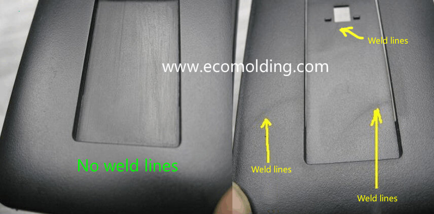
Definition of Flow Lines:
Flow lines, also known as flow marks Linear marks on the surface of a molded product, which indicates the flow direction of the molten plastic.
Injection Molding process
1.Insufficient Pressure / Holding Pressure
The injection pressure and the holding pressure are not high enough to press the solidified layer against the mold surface, thus leaving flow lines along the melt flow direction.
Increase the injection pressure and the
holding pressure, to press the solidified layer against the mold surface until
the product is molded, so as to prevent the occurrence of flow lines.
2.Improper Residence
Time
The plastic material stays in the barrel for a too short period of time, while
the melt temperature is low. Even if the cavity is barely filled, the plastic cannot
be compacted during pressure holding, thus leaving flow lines along the melt
flow direction.
The Shot-to-Barrel Ratio should be kept
between 1/1.5 and 1/4.
3.Improper Cycle Time
When the cycle time is too short, the plastic is not sufficiently heated in the
material barrel, and the temperature of the melt is low. Even though the cavity
is barely filled, the plastic cannot be compacted during pressure holding, thus
leaving flow lines along the melt flow direction
The cycle time is extended until the plastic is fully melted, and the temperature of the melt is high enough to prevent flow lines along the melt flow direction.
4.Barrel Temperature Too Low
When the barrel temperature is too low, the melt temperature will be low, and the injection pressure and holding pressure will not be high enough to press the solidified layer against the mold surface, thus leaving flow lines along the melt flow direction.
Increase the material temperature,
injection pressure and holding pressure to press the solidified layer against
the mold surface until the product is molded, so as to prevent the occurrence
of flow lines. The material temperature can be set by reference to material supplier’s
recommendations.
The material barrel is divided into
four zones: Rear, Center, Front and Nozzle. The material temperature settings
should be gradually raised as it moves forward. Increase by 6°C with
every zone forward.
When necessary, the temperature of the Nozzle and/or the Front are sometimes set to be the same as the Center temperature.
5.Nozzle Temperature Too Low
After absorbing the heat released by
the heating band, as well as the frictional heat generated by the relative
movement of the plastic molecules caused by the rotation of the screw, the
plastic in the barrel undergoes gradual temperature rises.
The last heating zone in the barrel is
the Nozzle, where the melt should reach the desired temperature, but it must be
moderately heated to maintain the optimal conditions.
If the nozzle temperature is not set
high enough, due to too much heat is taken away through the contact between the
nozzle and the mold, the material temperature will decrease, so that the
injection pressure and the holding pressure will not be high enough to press
the solidified layer against the mold surface, thus leaving flow lines along
the melt flow direction.
Raise the Nozzle temperature. The nozzle temperature is usually set to be 6°C higher than the Front temperature.
Mold
1.Mold Temperature Too Low
If the mold temperature is too low, the material temperature will drop very fast, so the injection pressure and the holding pressure will not be high enough to press the solidified layer against the mold surface, thus leaving flow lines along the melt flow direction.
Raise the mold temperature, maintain a
high material temperature, as well as high injection pressure and holding pressure
to press the solidified layer against the mold surface until the product is molded,
so as to prevent the occurrence of flow lines.
The mold temperature can be set from
the recommended values of the material supplier, with an increment of 6°C at
each adjustment. Then perform 10 shots, and after the injection molding is
stable, decide whether further adjustment is necessary according to the result.
2. Sizes
of the Sprue, the Runner and/or the Gate
If
the sprue, the runner, and/or the gate are too small, the flow resistance will
be increased. And, if the injection pressure is not high enough, the
advancement of the melt front will become slower and slower, and the plastic
will become colder and colder, so that the insufficient injection pressure and
holding pressure will not be able to press the solidified layer against the mold
surface, thus leaving flow lines along the melt flow direction.
It
is a feasible way to simulate and analyze the filling status of the different
melt transfer systems (including the sprue, the runner and the gate) on a
computer with CAE (such as, C-MOLD), to find out the ideal sprue, runner, and
gate sizes (including length and section related dimensions, such as diameter,
etc.)
3. Insufficient
Venting
Insufficient
venting will cause the melt filling to be blocked, and the melt front will not
be able to press the solidified layer against the mold surface, thus leaving flow
lines along the melt flow direction.
Start
venting at the end of each runner section, which removes a large amount of gas
before filling the cavity.
The cavity venting should not be neglected. Consider adding vents on the parting surface opposite to the gate. Correspondingly, consider adding venting ejector pins at the end of the product blind hole.
Simulate
melt filling through CAE (such as, C-MOLD), which helps us quickly find out all
possible last filled areas, i.e., the areas where vents must be added. The
addition of a vacuum system for air extracting before and during filling is an
effective venting method.
For some textured products, this may be the only way of venting.
Plastic Material
1.Poor
Fluidity
The mold cavity with a large flow length to thickness ratio must be filled with the plastic that features great fluidity. If the fluidity of the plastic is not good enough, the melt will be flowing slower and slower, colder and colder, so that the injection pressure and the holding pressure are not high enough to press the solidified layer against the mold surface, thus leaving flow lines along the melt flow direction. Material suppliers are able to offer professional recommendations according to specific designs:
The
most flowable plastic is selected on condition that no flashing is caused.
2.Improper
Application of Molding Lubricant
Usually,
the lubricant content is below 1%. When the flow length to wall thickness ratio
is large, the lubricant content must be moderately increased to ensure that the
solidified layer is pressed against the mold surface until the product is molded,
so as to prevent the occurrence of flow lines. The lubricant must be increased
upon agreement with the material supplier.
Operator
1. Bad
Habits
Inconsistent
molding result will occur if the operator switches the door of the injection
molding machine too early or too late. When the barrel heater tries to
replenish heat in time due to irregular heat loss, the plastic temperature will
not be uniform, thus causing the cold spot. It is not easy for the injection
pressure and the holding pressure to press the solidified layer around the cold
spot against the mold surface, thus leaving flow lines along the melt flow
direction. Usually, the operator should be constantly educated to let everyone know
the troubles caused by inconsistent molding cycles and recognize the importance
of maintaining best molding practices. Appropriate work shifts are able to prevent
operators from making mistakes due to exhaustless or distraction. Automated
production with robots or the like is a way to maintain a consistent molding cycle.