How to choose proper plastic molding types for your product?

Different plastic materials are being used to produce different objects in the manufacturing industry nowadays, and the manufacturing of each part needs a unique plastic molding process that can form the part on basis of its specs. Before you produce a plastic product, you need to determine the specific plastic molding process that would best address your production needs. In this article, we offer a general overview on 5 different plastic molding types, their strengths and specific applications.

plastic molding china

Blow Molding – applicable for production of hollow items, e.g. bottles

Blow molding is often applied to glass blowing, in which a parison (heated piece of plastic, usually a tube) is air inflated. The plastic material is pushed by air against the mold to get the desired shape. After cooling, the plastic part will be ejected.

This molding process is mainly used to produce one-piece hollow items in a high volume. It is the right process for you to make a lot of plastic bottles. The blow molding process is able to create thin-walled containers in a very consistent and yet economical way.

Compression Molding – applicable for production of larger items, e.g. automotive spare parts

As its name indicates, in this molding process, the heated plastic material will be placed in a heated mold, which will compress it into the desired shape. Though often coming in sheets, the plastic material can also be in bulk. The integrity of the final product is maintained by curing (heating). Like other molding processes, after the part is shaped, it will be ejected. In the circumstance where plastic sheets are used, the plastic material needs to be trimmed in the mold before part removal.

Compression molding is designed to deal with high-strength compounds, e.g. thermosetting resins, fiberglass and reinforced plastic materials. In the compression molding process, the application of the materials with outstanding strength properties makes it the most appropriate process for the production of auto parts.

Extrusion Molding – applicable for production of long hollow objects, such as tubes, pipes and straws

Different from other plastic molding types which get the plastic materials into a mold through extrusion, extrusion molding, as its name indicates, extrudes the molten plastic into a die, instead of a mold, to determine the shape of the final product.

The extrusion molding process forces the molten plastic material through a die to get the desired shapes with a fixed section. Many different shapes can be obtained through this process efficiently. Due to the fact that the plastic material needs to be melted and then solidified, only thermoplastics is strong enough to undergo the extrusion process. After cooling, the final extruded part can be cut or rolled for easier shipment.

Injection Molding – applicable for production of high-quality, high-volume parts

Among all plastic molding types, injection molding by far serves the most versatile purposes. Rated on basis of tonnage or pressure, the presses applied in the process differ in size, among which, the larger ones can be used for production of auto parts, while the smaller ones can be applied to produce very precise parts, such as those for surgical purposes. Besides, a lot of different plastics and additives can be used to increase the flexibility of injection molding for designers and engineers.

With regard to the process itself, it is very straightforward, but a lot of enhancements and customization technologies are added for production of parts with the desired surface finish and structure. The injection molds are generally made from steel and designed with cavities to form the part. During this process, molten plastic is injected into the mold, and filled into mold cavities. After cooling, the part will be ejected by ejector pins.

In this method, the cost of the mold itself is relatively high, but the cost of every part is rather low. Cost effective part, diversified resin and finish options have made the injection molding process a popular technique in the present manufacturing industry.

Rotational Molding (AKA Rotomolding) – applicable for production of large, hollow, one-piece items

Rotational molding coats the mold interior to form the desired part by using high temperatures and rotational movements. In this process, the mold rotates constantly to create the centrifugal force that is used to form even-walled parts. Though not a very fast moving process, it is an ideal method for manufacturing of large hollow containers, e.g. tanks. In addition, it is a more cost effective way for production of particular parts, when compared with other molding types. In this very process, little material is wasted and excess material can be recycled, making it not only economical, but also environmentally friendly.


Every plastic molding types has its unique advantages and disadvantages. Designers and engineers need to keep these differences and options in mind when planning for the most appropriate plastic molding types. Mold makers should be able to provide more in-depth insights into what best fits a particular project, be it applications or materials.

Different plastic molding process for plastic product

Plastic refers to the numerous organic synthetic materials that are mostly polymers of high molecular weight. Currently, it is one of the 3 synthetic materials that are indispensable for our day-to-day life, while the other 2 are synthetic rubber and synthetic fiber. Natural or synthetic resin, the main ingredient of plastic, is often mixed with a variety of additives, so that the material can be molded into desired shapes under certain temperature and pressure conditions, and maintain the shape at room temperature. As a high molecular compound, plastic molding can be processed with various methods, each of which is a blend of pros and cons, and suitable for specific applications. Now, let’s see how plastic is molded through some relevant interesting animations.

Injection Molding

Injection molding is a parts manufacturing process by injecting plastic molding material into a mold, of which the main method applied is injection molding. In this process, the plastic is loaded into a hopper, which will then feed the plastic into a heated injection unit. After being pushed through a long chamber with a reciprocating screw, the plastic material is melted into fluid. An injection nozzle is located at the end of the chamber, through which molten plastic is forced into a cold, closed mold. After the plastic is cooled and solidified, the semi-finished product will be ejected from the mold.

Plastic Extrusion

Plastic extrusion is a process for massive production, in which the plastic material is melted into a continuous shape. The extrusion process is usually applied to produce films, continuous sheets, pipes, profiles, bars, coating wires, filaments, cords and cables, etc. Together with the injection molding machine, the dried plastic material is loaded into a hopper and fed into a long heating chamber. At the end of the chamber, the material is forced out from a small opening or into a mold that’s in the shape of the desired product. As the plastic leaves the mold, it will be cooled down on a conveyor belt. A blower is sometimes involved in this process to facilitate cooling.

 Blow Molding

Blow molding process is applied to produce hollowed plastic products. Making use of air pressure, this post-forming technology blows the rubbery state parison in a closed cavity into a hollowed product.

Thermoforming

Thermoforming is a special manufacturing process which shapes the thermoplastic material into various products. The plastic sheet fixed on a frame is heated, softened, and then pressed against the molding surface under an external force, so as to mold it into the desired shape. After being cooled and trimmed, the desired product is obtained. This process is also applicable to rubber manufacturing. In recent years, thermoforming has witnessed all-new progress, e.g. the continuous production technology from sheet extrusion to thermoforming.

The 2nd animation shows the thermoforming process that involves 2 plastic sheets.

Compression Molding

Compression molding is the most commonly applied process for thermosetting materials. Usually, it is not applied to thermoplastics. In this process, the material is compressed into the desired shape. Plastic molding powder and other additives are added into the mixture to create special properties. When the mold is closed and heated, the material will be hardened to form the desired shape. The appropriate temperature, pressure and time duration applied in the process is dependent on the desired result.

Calendering

Calendering is a finishing process of heavy leather. When heated, the plasticity of the fiber is utilized to smoothen textile surface or create fine-grained parallel diagonals on the surface, so as to improve textile glossiness. After feeding, the material is heated and softened, then shaped into a sheet or film, and finally cooled down and rolled up. The most commonly calendered material is PVC.

Pultrusion

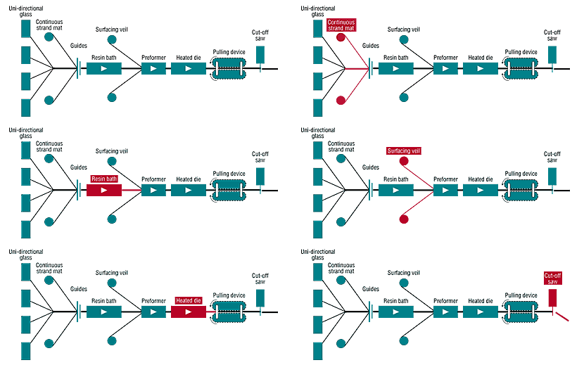
Pultrusion refers to the process where the blank is put under an uneven pressure from 3 different directions, and then extruded from mold opening or crevice, so as to reduce the sectional area and increase the length for production of the desired product. This blank forming process is referred to as pultrusion.

Vacuum Forming

Often known as suction forming, vacuum forming is a plastic processing technology by which a hard plastic sheet is vacuum-compressed against the mold surface after being heated and softened. After cooling, the desired product is produced. This process is widely applied in industries like plastic packaging, lighting, advertising, decoration and more.

Rotational Molding

Also known as rotational moulding or rotomolding, the rotational plastic molding process firstly feeds the plastic material into the mold, which will keep rotating along the 2 vertical axes while being heated. Under the influence of both gravity and heat, the plastic inside the mold will gradually and evenly spread over and stick to the entire surface of the mold cavity. After cooling and ejection, the desired product will be made.


All copyright reserved by injection molding company Eco Molding

Injection Molding Gate Types(Updated)

Injection molding gate design Considerations:

1.A small opening between the runner and the mold cavity, of which the location, quantity, shape and size, etc. have a direct influence on product appearance, dimensional accuracy, physical characteristics and injection molding efficiency.

2.The size of an injection molding gate is dependent on product weight, material properties and gate shapes. The length, depth and width of a gate should be minimized on condition that product mechanical performance and molding efficiency can be guaranteed.

3.If the gate is too small, product defects like insufficient filling, shrinkage, sinking and weld lines will tend to occur, and molding shrinkage will increase.

4.If the gate is too big, excessive residual stress will be caused around the gate, leading to product deformation or cracks, and also it will not be easy to remove the gate.

Injection Molding Gate Types

1.Direct Gate: Melt enters the mold cavity directly through the sprue, suitable for shell-/box-shaped molds that feature a deep single cavity. With a short runner, it possesses the advantages of little pressure loss and convenient venting, but it is not easy to remove the gate, with noticeable marks left.

direct gate,sprue gate design    direct gate,sprue gate

2.Fan Gate: The gate gets larger to become a fan shape from the runner to the mold cavity direction. This type of gate is suitable for the production of slender or flat and thin products, because it is able to reduce flow marks and directional stress. The angle of the fan is dependent on product shapes. The cross sectional area of the gate cannot be larger than that of the runner.

fan gate    fan gate

3.Pin Point Gate: The type of gate that has a sectional area as small as that of a pin. It is usually used for plastic materials that boast excellent fluidity. Normally, the length of the gate is no larger than its diameter, so the gate will be automatically cut off after mold release, making it unnecessary for additional trimming. It is widely used for the production of covers, housings and large-area products, thanks to the feature that there is no apparent gate mark. It allows the mold one more parting surface to make it easier for gate removal. The disadvantage is that the small size gate may lead to loss of pressure and cause some molding defects (flow marks, burnt marks and black spots, etc.). The shapes of pin point gate include diamond, single-point, double-point and multi-point, etc. It uses the three-plate mold, with a pore size of about 0.25 – 1.5mm.

point gatepoint gate

4.Side Gate: Usually located on one side of the mold. Material is fed in from the inside or outside of the parting surface. Often with a rectangular section, this type of gate is suitable for a multi-cavity mold. Usually trimmed manually, the gate thickness (a fixed thickness or a declining thickness) is about 50% – 75% of product thickness.

side gateside gate

5.Sub Gate: This type of gate is usually inclined and lurks on one side of the parting surface. Material is fed in from product side or the inside. The pin sized gate will be cut off automatically during mold release, thus suitable for automatic production. The sub gates have several variations.

  • Sub gate in cav side

submarine gate

  • Sub gate in core side

submarine gate

  • Banana gate

banana gate

All copyright reserved by injection molding manufacturer Eco Molding

Hot runner systems types of plastic injection mold

How the Hot Runner Systems Works

The cold runner of a plastic injection mold refers to the section between the mold inlet and the gate. The molten plastic maintains its fluidity inside the runner by virtue of the injection pressure and its own heat. However, as a part of the molding material, the runner is not a product. As a result, when designing a mold, we need to consider not only the filling effects, but also the material-saving effect produced by shortening or downsizing the runner; but in actuality, it is not easy for us to have the best of both worlds.

hot runner systems of plastic injection mold

Types & Application of Hot Runners

When applying the hot runner technology, the proper selection of gate type is of critical importance, because gate type directly determines the selection of hot runner components as well as manufacturing and application of molds. Therefore, the hot runner system can be classified into 3 types based on the gate type, i.e. (1) hot tip hot runner system, (2) sprue gating hot runner system and (3) valve gating hot runner system.

Hot Tip Hot Runner Systems

Hot Tip Hot Runner System of plastic injection mold

It is the most widely applied hot runner , since each supplier provides this system. Though systems from different suppliers feature different nozzle and nozzle insert of different shapes and sizes, they work precisely the same way, which is precisely adjusting and controlling the plastic injection molding temperature at the gate through an approach that combines the insert hot tip at the front of the nozzle with the cooling system. As a result, the material and design shape of the nozzle insert hot tip are of great importance. Each hot runner supplier has invested a lot in the R&D of hot tip.

The hot tip hot runner system can be applied to process the majority of crystalline and non-crystalline plastic materials, such as PP, PE, PS, LCP, PA, PET, PBT, PEEK, POM, PEI, PMMA, ABSPVC, PC, PSU and TPU, etc. Generally speaking, the hot tip gate is used to produce medium and small sized parts, esp. suitable for production of micro parts. The sectional diameter of the gate usually measures between 0.5mm and 2.0mm.

Sprue Gating Hot Runner Systems

Sprue Gating Hot Runner Systems of plastic injection mold

In the sprue gating hot runner, the plastic material enters the mold cavity through the smooth open pipe. Melt flow pressure loss in the gate area is slight. The sprue gating hot runner system is more suitable for production of medium and large sized parts. The advantages that the sprue gating hot runner system brings is that the molten plastic undergoes a low shear rate when flowing through the gate, so the molded part will feature a smaller residue stress, leading to a minor deformation rate and a greater mechanical strength of the part. Compared with the hot tip hot runner system, the gate mark might be more visible due to the larger size of the sprue gating. So, the sprue gating hot runner system is usually applied to internal parts or components that do not have high aesthetic requirements on gate appearance. Also, the sprue gating is often used in combination with the cold runner, i.e. taking the sprue nozzle as the main runner, and designing the sprue gating along the cold runner. In the application, the sprue gating can be bigger to facilitate plastic flow, because no one cares about the gate marks on the cold runner.

Valve Gating Hot Runner Systems

Valve Gating Hot Runner System of plastic injection mold

The valve gating hot runner is another widely applied hot runner systems that is supplied by global mainstream suppliers. Through the valve pin controller, this system mechanically opens or closes the gate at the pre-set time. This types of hot runner system possesses the advantages beyond the reach of the previous 2 systems (Hot Tip Hot Runner System & Sprue Gating Hot Runner System), such as controlling the gate open/close time manually, allowing a smooth and glossy gate, and expanding the technical scope of hot runner application.

Injection Mold Cooling Systems

 The Purpose of  Injection Mold Cooling Systems 

The injection mold cooling system purpose is to ensure uniform cooling of the molded product and then eject the product out within a short period of time. The layout of the cooling channel plays an important role in the injection molding quality as well as the production cycle (cost) of a product.

  • Influence on Quality: During the injection molding process, the cooling channel is used to control mold temperature, of which the fluctuation has a direct influence on product shrinkage, deformation, dimensional stability, mechanical strength, residue cracks and surface quality, etc. Mainly include: surface glossiness, residue stress, crystallinity and thermal flexure.
  • Influence on Production Cycle: An injection molding cycle is mainly composed of the following steps. Reducing the cooling time means an improvement in the injection molding efficiency.

cooling time

Injection Molding Cooling Types and Layout:

1,Cooling line in core /cavity inserts

Injection mold cooling system for injection mold

2,Connecting cooling line between mold plates and inserts

cooling channel system between mold plates and inserts

3,Different cooling line type

cooling system for plastic injection mold

4,Cooling tower

cooling tower design for plastic injection mold

5,Cooling line in lifter

cooling line in lifter of plastic injection mold

6,Cooling line in slider

cooling line in sliders of plastic injection mold

Injection Mold Venting Slot Design

During the plastic injection mold trial process, defects like short-filling, trapped air burns, high internal stress, flow marks and weld lines often occur. For those problems, the first solution would be adjustment of the plastic injection molding process, and another consideration would be the reasonable design of the mold gate. Once both of these problems are solved, the possible trouble could mainly lie in  injection mold venting, to which the main solution would be the design of venting slots.

Injection mold venting system

The Function & Design of  Injection molding Venting

1. The Functions of Injection Mold Venting

A venting slot mainly serves 2 purposes, 1) Removing air from the mold cavity during the injection molding process; 2) removing the various gases produced during the material heating process. Venting slots are of great importance especially to thin-walled products as well as the locations far from the gate. Besides, venting slots also very important for small size or precision parts, because in addition to preventing product surface burns and short filling, they eliminate various product defects and reduce mold contamination. So, what is sufficient air venting for a plastic mold? Generally speaking, when there are no burn marks on product surface at the highest injection speed, the venting effect of the mold cavity would be considered sufficient.

2. Venting Methods

There are many ways to vent the mold cavity, but each has to guarantee that: first, the dimensional design is able to prevent material from entering the slot during the venting process; second, it is able to prevent clogging at the same time. Therefore, for the 6 – 12mm long or above (measuring from the inner surface of the cavity to the outer edge of the mold cavity) slot portion, the height has to be increased by 0.25 – 0.4mm. Besides, it would be harmful if there are too many venting slots, because if the clamping force applied on the unslotted area of the cavity parting surface is too high, cold material flow in the cavity or cracking would occur, which is very dangerous. In addition to venting the mold cavity from the parting surface, the venting purpose can also be achieved by machining venting slots at the melt flow end in the gating system, as well as leaving venting clearance around the ejector pin. The depth, width and location of the venting slots play an important role in defining product quality – flash will occur if not appropriately designed. As a result, the size of the above-mention clearance should be able to prevent flash occurring around the ejector pin. It should be specially noted that: when designing venting for parts like gears, even the slightest flash is not allowed. So, the following venting methods should be adopted for such parts: ① thoroughly remove air in the runner; ② apply shot peening treatment to the parting surface with the 200# silicon carbide abrasives. Besides, setting up venting slots at the melt flow end in the gating system mainly refers to the venting slots at end of the branch runners, of which the width should be equivalent to that of the branch runner while the height varies with materials.

3. Design Approach

Based on many years of experience in injection mold design and mold trial, this article simply introduces the designs of several types of venting slots, as shown in figure 1. With regard to the mold for production of complicated shaped products, venting slot setup should better be determined after several rounds of mold trials. Among all mold structural designs, the integral structure features the poorest venting effect. The following venting methods can be applied for integral cores/cavities: ① make use of the slot or insert location in the mold cavity; ② make use of the lateral insert crevice; ③ design local area into a spiral; ④ mount the batten horizontally and set up technological holes; ⑤ when it is extremely difficult to expel the air out of the mold, an insert should be adopted. If it is not easy to machine a vent slot in some locations of a mold, such as in the corners, the insert molding process may be appropriately applied on condition that product appearance and precision are not affected. This method not only helps with venting, but is also able to lower the difficulty level for machining, and convenient for maintenance.

The chart of mold venting depth for different plastic

Conclusion

Properly designed venting slots are able to remarkably reduce injection pressure, injection time, pressure holding time and clamping force, thus making the plastic injection molding process a lot easier by improving production efficiency, lowering production costs and reducing machine energy consumption.

Plastic injection mold steel materials selection principle

injection mold steel

Plastic Injection Mold Steel Selection for Molding Components

  1. Molding components refer to the mold parts or components which have a direct contact with the plastic materials to form a product, such as mold cavities, mold cores, sliders, inserts and lifters, etc.
  1. The steel quality of the molding components has a direct influence on mold quality and service life, and determines the appearance and quality of a plastic injection molded product, so plastic injection mold making factory must make careful selection. Generally speaking, materials have to be selected based on contract stipulations, client requests, as well as product / mold requirements and characteristics.
  1. Principle for steel selection of molding components: different types of steels need to be selected based on types of plastic, product shapes / dimensions, product appearance / quality / application requirements and production scale, etc., while paying attention to the various material performances like machining, polishing, welding, texturing, deflection and abrasion resistance, and at the same time taking economy and mold manufacturing conditions/process into consideration.
  1. With regard to the plastic molds for production of transparent plastic parts, the mold cavity and core need to select high-grade imported steel materials that boast an outstanding mirror polishing performance, such as 718 (P20+Ni), NAK80 (P21), S136 (420) and H13 steels, among which, 718 and NAK80 are pre-hardened, so preheat is not necessary; S136 and H13 steels are annealed usually with a hardness between HB160 and 200, so vacuumquenching and tempering are needed after rough machining; the hardness of S136 steels is usually between HRC40 and 50, while that of H13 steels is between HRC45 and 55.
  1. With regard to the molds for production of products that have high requirements on surface quality, long service life and large production scale, the material selection for the molding components should be made according to:

a) The mold cavity needs to select high-grade imported plastic injection mold steel materials that boast an outstanding mirror polishing performance, such as 718 (P20+Ni), NAK80 (P21) which are pre-hardened, so preheat is not necessary.

b) The mold core may select medium-/low-grade imported P20 or P20+Ni steel materials, such as 618, 738, 2738, 638 and 318 which are all pre-hardened; for molds that are in small-scale production, domestically produced mold steels or high quality imported carbon steels like S50C and S55C can be used.

  1. With regard to the molds for production of average surface quality products, the molding components may select the following steel materials:
  • a) The mold cavity and mold core of small-sized precision molds may select medium-grade imported steel materials, such as P20 or P20+Ni steels.
  • b) For medium and large-sized molds, when the molding steel do not have special requirements on steels, the mold cavity may select medium-/low-grade imported P20 or P20+Ni steel materials; while the mold core may select low-grade imported P20 steels or high quality imported carbon steels like S50C and S55C.
  • c) For textured cavities, try to avoid the application of the P20+Ni steel with the no. of 2738 (738) when producing matt texture.
  1. With regard to internal parts that do not have requirements on surface quality, when molding materials do not have special requirements on mold steels, the mold cavity may select low-grade imported P20 or P20+Ni steels, or the high quality imported carbon steels like S50C and S55C, or the domestically produced plastic mold steels; and the mold core may select high quality imported/domestic carbon steels.
  1. For corrosive plastic materials which contain fluorine or chlorine, or the plastic materials that contain various additives like flame retardants, the mold may select imported corrosion resistant steels when the product needs to be manufactured to high requirements, or select domestically produced corrosion resistant steels in case of general requirements.
  1. If the plastic materials produce a strong abrasion or impact effect on mold steel, for example nylon + glass fiber, the mold needs to select imported or domestically produced H13 steels which are highly abrasion/heat/stretch resistant and highly resilient.
  1. For insert molding, the mold may select the same material as the insert. For the mold part that is hard to cool or has high requirements on cooling, the insert materials should choose be-bronze or aluminum alloy.
  1. For the moving parts in a mold, which are involved in molding, the material should be selected according to:
  •  Imported high-grade high-polishing steels, like 718 and NAK80, should be selected for production of plastic products.
  • Usually, medium-grade imported steel materials with a high hardness and a high strength should be selected for opaque products, such as 618, 738, 2738, 638 and 318, etc., of which the surface should be nitrided with a depth of 0.15 – 0.2mm and a hardness of HV700 – 900.
  • If the mold has a low requirement, low-grade imported or domestic plastic injection mold steel materials can be selected, which is usually nitrided with a hardness of HV600 – 800.


Plastic Injection Mold Steel for Non-molding Componentsmold making factory in china

  1. Selection of mold base materials is subject to the mold base standards; and the mold plate usually employs the imported S50C steel or the domestically produced SM45 steel, which is required of a uniform hardness of HB160 – 200 and a small internal stress while not being prone to deformation; the guide pin material can be GCr15 or SUJ2 with a hardness of HRC56 – 62. The materials of guide sleeve, ejector guide pin, ejector guide bush and return pin can be GCr15 or SUJ2 with a hardness of HRC56 – 62; or T8A and T10A with a hardness of HRC52 – 56.
  1. For the general structural members of a mold, such as ejector locating ring, vertical pillar, ejector stopper, tie bar and locking block, if there are no special requirements, domestically produced normalized SM45 steel with a hardness of HB160 – 200 can be applied, which does not need to be preheated.
  1. In a mold, the parts that have higher requirements on hardness, strength and abrasion resistance, such as sprue bushing, wedge block, wear block and slide wear plate, carbon tool steels or high quality carbon tool steels like T8A and T10A can be selected. These types of plastic injection mold steel need to be quenched during application to enhance their hardness and abrasion resistance.

How To Design Parting Line for Injection Molding?

Type of Injection mold parting line

1.Horizontal parting line

parting line in plastic injection mold

2.Oblique parting line

parting line of plastic injection mold

3.Curve parting line

curve parting line of plastic injection mold

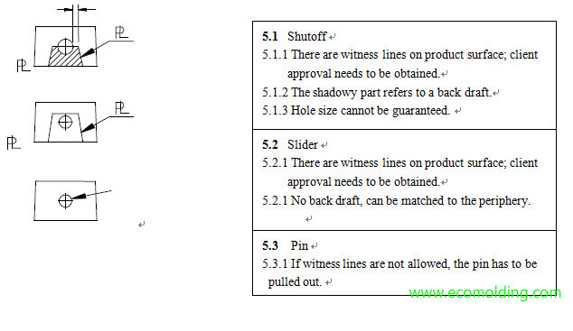
4.Injection mold parting line on shut off holes

shut off parting line in plastic injection mold

5.Injection mold parting line on side holes

parting line for side holes in plastic injection molding

General Principles for Selection of Main Parting line

  1. Protect the Inserts

Usually, product disassembly needs to be considered before selecting the main parting surface, i.e. identify the secondary parting surfaces, and find out the lowest surface of the cavity insert which will serve as the main parting surface. Try not to let the cavity core enter plate B from plate A, so as to prevent the insert from being damaged during mold disassembly.

  1. Simplify mold structure, increase mold plate strength
  2. Identify the main parting surface based on the special structure of a plastic mold
  3. To prevent the parting line locks on the 4 corners of the insert from being wrongly assembled, the lock at the base corner needs to be 1.0mm larger.
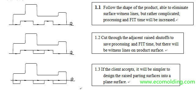
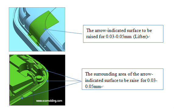
  4. When the main mating surface of a product exists on 2 work pieces concurrently, the piece inside the profile surface needs to be raised for 0.03 – 0.05mm, so as to prevent apparent mismatch. (See the following figures)

parting line for lifter in plastic injection mold

  1. At the joint between the core and the cavity, the melt in the cavity needs to be reduced by 0.03-0.05mm, so as to prevent mismatch of product kiss-off holes caused by processing tolerances.

General Principles for Selection of Secondary parting  line

  1. Meet client needs, without affecting product appearance & performance
  2. Convenient for mold release
  3. Facilitate venting
  4. Minimize side undercuts, simplify mold structure
  5. Convenient for processing
  6. Convenient for surface treatment of the mold insert

The spring for plastic injection mold

As an elastic component, the spring plays a very important role in a plastic injection mold, because a properly located spring is able to provide the necessary driving force that the mold needs. For example, when the ejection mechanism completes the ejection action of a plastic part, a spring can be applied to force the ejection mechanism back to its original position, so as to ensure the work process goes smoothly, i.e. the so-called return spring. To meet this purpose, different spring designs are required for different structural locations.

Usually, rectangular springs are used in plastic injection molds. When mounted in the same space, the loading capacity of a rectangular spring is about 45% higher than that of a cylindrical spring, while the deflection is 13% – 14% larger. A proper spring design is able to simplify mold structure, lower mold maintenance costs and thus guarantee a smooth production process. Through actual examples, this article will introduce the design and selection of springs for the ejection mechanism.

Design Requirements of Return Springs

To meet the work requirements of return springs, the following points should be taken into consideration during spring design:

1. Select the appropriate compression deflection. Spring compression deflection refers to the ratio between its compressed length (L1) to its free length (L), of which the value has a direct influence on spring service life as well as the loading capacity.As an elastic component, one of the biggest disadvantages in spring application is spring failure. During operation, the higher the deflection or compression, the shorter the service life; if the deflection is too low, the spring will not be able to provide sufficient return force for completion of the return task.

Based on the loading capacity, mold springs mainly fall in the categories of minimal load (TL, yellow), light load (TF, blue), medium load (TM, red), heavy load (TH, green) and extra heavy load (TB, brown). Different categories are designed in different colors to indicate springs with different service life as well as different deflections.

2. Ensure spring travel stability. Appropriately designed mounting holes and mandrel sizes are mainly applied to guide the spring and limit its deflection.However, a spring will be over restricted if the mounting holes are too small. At the same time, the mandrel size influences the inner diameter of a spring. Since rectangular springs feature smaller inner diameter, the outer diameter should be as large as possible.

3.Set appropriate spring preload. Preload is also known as preload length. In the preload status, a return spring can effectively maintain stability during the work process by preventing spring fatigue and increasing spring service life. A preload of 10 – 5mm may be applied when a return spring is concerned.


Design Process of Return Springs

1. Select the appropriate compression deflection. Considering the service life and the minimum ejection travel distance, the compression deflection of a return spring usually ranges from 30% to 40%. This value leads to the result that only the light load blue (TF series) springs are applicable when choosing return springs.

2. Outer diameter of a spring. The outer diameter is one the main technical parameters of a spring, of which the value is usually influenced by mold size and mandrel size. The bigger the mold is, the larger the outer diameter of a spring is.

3. Free length of a spring. Free length of a spring is one of the basic parameters for spring selection. Springs of the same outer diameter may have different free lengths. The free length of a spring is influenced by product ejection travel distance – it has to be longer than the travel distance of the ejection mechanism or the spring will not be able to work properly. As a result, the compression of a return spring should at least be the sum of the ejection travel distance and the preload length.

The runner design

The Runner Design Concept

  • The runner refers to the melt flow passageway between the end of the main runner and the gate, which is used to change melt flow direction and allocate it to each cavity in a stable and balanced way.
  • The basic design principle of the branch runner is little pressure/heat loss, with the minimum quantity of plastic retained in the runner.
  • Sectional Shapes of the Branch Runner:

The runner design for plastic injection mold

–Circular, with the minimum specific surface area (runner surface area/runner volume), but during production, both sides of the mold plate need to be aligned.

–The commonly applied forms, trapezoid and U-shape are easy to process.

–Semicircle.

–Rectangle, larger specific surface area and high resistance to flow, thus seldom applied.

The Principle of the Runner Design

  • The runner is usually designed on either half of the plastic injection mold.
  • When considering the layout of the cavity and the branch runner, it is better to ensure that when projected on the parting surface, the geometric center of the total projection area of the cavity and the runner overlap with the center of the clamping force.
  • The internal surface roughness of the branch runner is 1.6. In this case, the outer layer melt flows faster than the inner layer melt inside the branch runner, which tends to cool down and thus form a heat insulation layer.
  • The sectional size of the branch runner is dependent on the plastic part size/type, injection speed, as well as the length of the branch runner.
  • Generally, when the diameter of a branch runner is smaller than 5 – 6mm, runner size will have a greater influence on fluidity; when the diameter is greater than 8mm, there will be little influence on fluidity.
  • If the branch runner is very long, it might be better to further extend the branch runner along the flow direction to form a cold slug well, so that the cold materials will not enter the cavity.
  • The branch runner cannot be too thin, or temperature/pressure loss will increase, which makes it hard to fill up the cavities far from the main runner.

The Runner Design Layout

In a multi-cavity layout, it needs to be guaranteed that the molten plastic can concurrently fill up each cavity in a uniform way. There are 2 layouts, i.e. balanced and unbalanced:

Balanced: uniform filling, with each cavity concurrently filled.

Unbalanced: The runner is designed to be short to save raw materials.

The runner layout design for plastic injection mold